- +86 19149417743
- Zhengzhou, Henan Province, China
- Mon-fri: 8am - 7pm
Get a quote

A stepper motor is a discrete value control motor that converts electrical pulse excitation signals into corresponding angular displacement or linear displacement. This kind of motor moves one step every time an electrical pulse is input, so it is also called a pulse motor.
The driving power supply of the stepper motor is composed of a variable frequency pulse signal source, a pulse distributor and a pulse amplifier, from which the driving power supply provides pulse current to the motor windings. The operating performance of the stepper motor depends on the good cooperation between the motor and the driving power supply.
The advantages of stepper motors are no accumulated errors, simple structure, easy use and maintenance, low manufacturing cost, and large capacity to drive load inertia. They are suitable for small and medium-sized machine tools and places where speed accuracy is not high. The disadvantage is low efficiency. , the fever is great and sometimes "out of step".
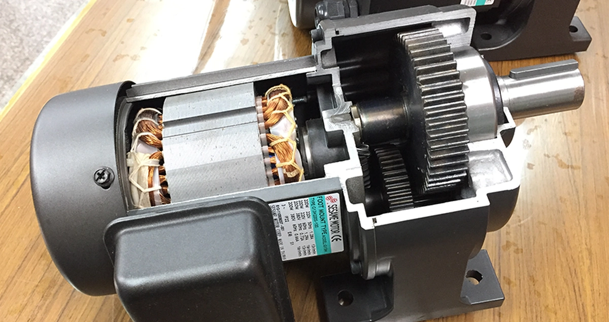
1. Electromechanical stepper motor
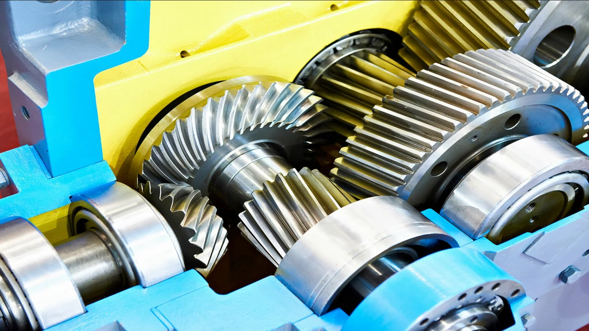
The electromechanical stepper motor is composed of core, coil, gear mechanism, etc. When the solenoid coil is energized, it will generate magnetic force, which will push its core to move. The output shaft will rotate by an angle through the gear mechanism, and the output shaft will be kept at the new working position through the anti-rotation gear. When the coil is energized again, the shaft will rotate by another angle. Perform step-by-step movements in sequence.2. Magnetoelectric stepper motor
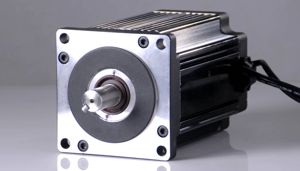
Magnetoelectric stepper motor has a simple structure, high reliability, low price and wide application. There are mainly permanent magnet type, magnetic resistance type and hybrid type.3. There are two types of linear stepper motors
reaction type and Sawyer type. The Sawyer linear stepper motor consists of a stationary part (called the reaction plate) and a moving part (called the mover). The reaction plate is made of soft magnetic material, with teeth and grooves evenly cut on it. The mover of the motor consists of a permanent magnet and two magnetic poles A and B with coils. The mover is supported by an air cushion to eliminate mechanical friction during movement, allowing the motor to run smoothly and improve positioning accuracy. The maximum moving speed of this kind of motor can reach 1.5 meters/second, the acceleration can reach 2g, and the positioning accuracy can reach more than 20 microns. Two Sawyer linear stepper motors are assembled vertically to form a planar motor. By giving different combinations of control currents to the two motors in the x-direction and y-direction (Figure 3), the motor can move in any geometric trajectory in the plane. A large automatic plotting machine is a new type of equipment that combines a computer and a flat motor. Planar motors can also be used in laser cutting systems, with control accuracy and resolution up to tens of microns.We use Figure 11.20 to illustrate the working principle of this kind of motor.

The stator of the reluctance stepper motor is equipped with polyphase excitation windings. Figure 11.20 is a schematic diagram of the most commonly used three-phase winding stepper motor. The three-phase winding forms 6 magnetic poles. The rotor is made of soft magnetic material and has 4 teeth. When the A-phase winding is energized, but the B and C phase windings are not energized, the magnetic flux tries to take the path of minimum reluctance to minimize the magnetic resistance of the magnetic circuit. Therefore, a reluctance torque is generated to make the axes of teeth 1 and 3 connect with the stator A. Phase poles aligned. At the next moment, energizing the B phase and cutting off the power supply to the A phase will align the axes of the rotor teeth 2 and 4 with the B phase magnetic poles, so the rotor will rotate 30° counterclockwise as a whole. Therefore, energizing the three windings in turn in the order ABC-A... will cause the rotor to rotate continuously in the counterclockwise direction. If power is applied in the sequence ACBA..., the rotor will rotate clockwise. From this, the following judgments can be obtained:
The step angle of each step in the above stepper motor model is 30°, which is difficult to meet the requirements of fine control. The actual motor adopts the structure as shown in Figure 11.21. In this structure, there are some evenly spaced small teeth on the pole arc of the stator magnetic pole, and the small teeth are also evenly distributed on the surface of the rotor. The pitch measured in angle between the small teeth of the rotor is exactly the same as the pitch of the stator. The so-called tooth pitch is the angle between the center lines of two adjacent teeth, also known as the tooth pitch angle DT=360°/Zr where DT-tooth pitch; Zr-the number of teeth of the rotor.
Due to the opening of these small teeth, the rotation of the rotor during winding switching can find a position with minimum reluctance within a range smaller than DT, thus greatly reducing the step angle and improving the resolution of motion.
From the analysis of Figure 11.20, it is noted that when the teeth of the rotor completely match the teeth of a certain magnetic pole, for an m-phase motor, the teeth of the rotor and the teeth of the other two-phase magnetic poles must be staggered by a pitch of 1/m. For a three-phase motor, when phase A is energized, the small teeth of the rotor and the small teeth on the B and C phase magnetic poles must be staggered by DT/3 in sequence. Under this constraint, the number of teeth of the rotor cannot be an arbitrary value, but must meet the following conditions:
Zr/2p=K±1/m, that is, Zr=2p (K±1/m)=2pK±2
where K -positive integer; p-polar pair number; m-phase number, p=m.
The motor stator in the working principle diagram of the hybrid stepper motor
has 4 teeth evenly distributed along the circumference. Coils are wound on the teeth and connected in pairs. The two rotor sections with different polarities have 3 teeth each. In the figure, the solid line represents the S segment and the dotted line represents the N segment. The two rotor segments are staggered by half a tooth pitch.
When there is no current in the winding, because the permanent magnets in the rotor always try to reduce the reluctance in the magnetic circuit, the rotor will tend to a limited number of positions until there is a tooth on each of the N-pole and S-pole rotors aligned with the stator magnetic pole. For the motor in the picture, there are 12 such positions. The torque that holds the rotor in these positions is usually not large and is called holding torque.

If there is a current flowing through one phase winding as shown in Figure 11.28(a), the N pole and S pole generated on the stator will attract the teeth on the opposite rotor segment. In this case, there are only 3 teeth that are the same as the number of rotor teeth. When the rotor is in a stable position, the torque that pulls the rotor away from the position is much larger, which is called locking torque.
Switch the energization mode from picture (a) to picture (b), and the stator magnetic field rotates 90 degrees. , will attract another pair of teeth, resulting in the rotor rotating 30 degrees. , equivalent to one full step. In diagram (b) to diagram (c), the excitation returns to the previous winding, but the current direction is reversed, allowing the rotor to advance one full step. In Figure (d), the second phase winding current can be reversed to move forward one step further. In this way, the rotor has gone through one tooth pitch. The steps are repeated from figure (d) to figure (a) to form a rotational motion of the motor, which requires 12 steps per revolution. Obviously, energizing the stator windings in the reverse order will cause the motor to reverse direction.
Usually the small teeth of the stator are evenly distributed at a different pitch than the rotor. In motors with a larger number of teeth (as shown in Figure 11.27), the tooth pitch of the stator and rotor is arranged so that only the two teeth on the opposite side of the rotor are 180 degrees apart from the two teeth. . The stator teeth are perfectly aligned. At the same time, 90 away. The stator and rotor teeth at the mechanical corners are completely staggered. For a hybrid motor with such a structure, the following formula can be used to calculate the number of steps per revolution N=┃NrNs/(Ns-Nr)┃where
N is the number of steps per revolution; Nr and Ns are the number of teeth of the rotor and stator respectively. For the example in Figure 11.27, Nr and Ns are 8 and 10 respectively, then it can be calculated that the motor has 40 steps per revolution and a step angle of 9.
Stepper motors are designed for precise displacement. In order to achieve higher precision, the efficiency must be low and the current high. It is not a DC motor that can run when powered on. Moreover, the stepper motor relies on a single chip to generate pulses to control the torque. The single-chip microcomputer itself has a small driving current and cannot drive the motor windings. A drive circuit must be used to generate a larger current. Direct driving will burn out the single-chip microcomputer.
 2024-03-06 17:12:12
Engineering
2024-03-06 17:12:12
Engineering
 2024-02-29 15:08:43
Engineering
2024-02-29 15:08:43
Engineering
 2024-02-27 10:12:57
Engineering
2024-02-27 10:12:57
Engineering